Saturday, May 3, 2008

GEEKZONE: Masking Layers by the Steps

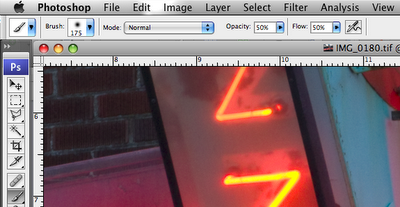
Step 1. Prepare the tools
Brush Settings:
Mode- Normal, Opacity- 50%, Flow- 50%
Foreground/Background color: white/black (default) .
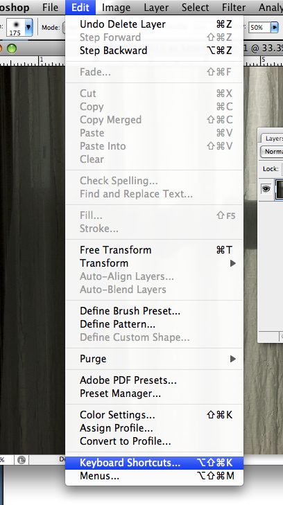
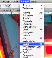
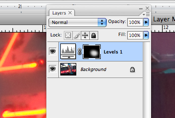
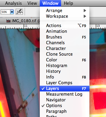
Layers Palette: visible. (Window>Layers checked)

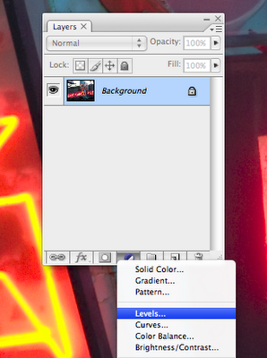
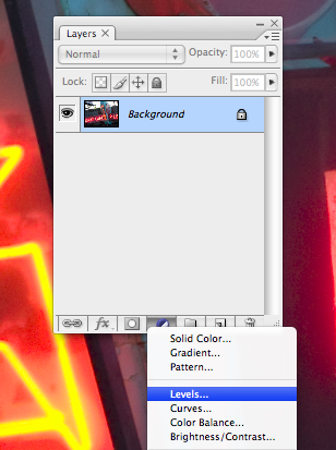
Step 2. Create Layer, and Mask.
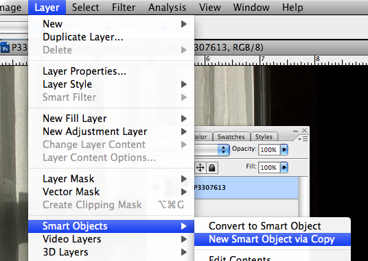
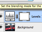
Select black/white circle (“Create new fill or adjustment layer”). Make adjustment… for example, make the image darker.
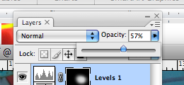
Select Mask (white rectangle next to Adjustment icon.) Turn black with keyboard shortcut Command I.

Step 3. Make Mask selection.
With the (now black) mask selected, use the Brush tool to “paint” white on the black mask, in areas that you want to become visible, or active. This shows a small area of our adjustment that will “show through”. If the adjustment makes the image darker, this is the only area that will be darker… etc.

Tips and Tricks.
“{“ and “}” makes your Brush a smaller and larger diameter.
Command x switches the foreground/background colors.
“Painting” black over a white area of the mask “covers” the edit, allowing you to fix and change your selection.
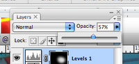
The “Opacity” button on the Layers palette (different from the “Opacity setting for the Brush Tool) allows you to decrease the overall effect of the Adjustment Layer.


Labels: , , ,

Wednesday, April 30, 2008

GEEKZONE: Controlling the Histogram- EV +/-

My students hear it all the time. The single most powerful tool of digital imaging is the histogram, whether on the camera, or in “Levels” in Photoshop.

A histogram is a graph of the tonal values in an image. Simply put, the histogram on the camera lets me see the actual tonal values of the photograph, as I’m taking the picture. The histogram in Levels lets me see exactly where tones fall, and with a little experience, how they will print. The trick is learning how to understand the histogram, and how to use it.

Let’s look at an image that is low contrast, and look at the histogram we get. The tones in the image range from medium-dark gray to medium light gray, and the histogram shows that very clearly. None of my tones map out to the extremes of the “graph”. Nothing hits the far-left, pure black, and nothing hits the white at the far right. My camera meter tries to average everything out, what my Dad used to call trying to “see everything as gray”. It will measure the entire scene and place the range of values, from light to dark, smack in the middle, giving me this histogram that sits right in the center of the graph.


I can shoot a black dog and my camera will try to make her gray. A snowy field? Gray. Here’s a great example. Look at the thin lines to the left and right of the main black area of the graph. They are perfectly centered between the pure black and pure white extremes.

This, if you let it, will print just as you see it. Gray. You can adjust it in Photoshop, of course, but the better thing to do is to capture it where you want it, mapping the whites to the white values, the grays to the gray values, and that is the question… how do you tell the camera where you want to put these tones?

The answer is with the EV +/- control. Let’s assume you want to shoot with Auto Exposure, either in Shutter or Aperture Priority. The EV control lets you tell the camera to over- or under-expose the image, or simply put, make it brighter or darker. Going to the “+” side makes my snowy scene brighter, it pushes my tones up on the histogram and makes the gray values more white. A little practice will show you how much to boost it, but the histogram on the camera will show you precisely what the effect of the boost will be.

Here’s what it looks like when I boost the exposure “+1”. Immediately you can see the white snow reads, and even prints here as white, but more importantly, I can see on my histogram exactly how white that is. It’s just a small amount away from the pure white of the far right of my graph, indicating that it still has tones… the file is not “blown out”, or reading no detail in the highlights.


Watching the histogram on the camera, and judicious use of the EV +/- control, along with my vision of the final photograph allows me to capture the information I need, in the places I want it, to get the most information from my capture and ultimately make the highest quality photograph.

I remember seeing a great film about Ansel Adams, and there was this scene where he took a print out of the wash and popped it into the microwave (then, a very new contraption, often called the “Radar Range”). By drying it down, he could then read the blacks and whites in the print (with a meter) to make sure he’s getting the purest white and deepest black out of his paper and his negative. This is exactly what the histogram gives us.

Imagine if Ansel had that information at his fingertips as he was making his exposures! Crazy stuff!

Labels: , , , , ,

Monday, April 28, 2008

Linearization- A Brief Note

In the discussion about profiling and calibration, I think the term “linearization” gets a little lost. Linearization is sometime described as calibration, or standardization. I’ve even quoted Bill Atkinson as saying “the Stylus 9800 printers are extremely linear, they are the closest thing yet to the great mother printer in Japan”, the implication being that it is more of a standardization process. It’s that, in part, but really it’s more of an issue of making a smooth “response ramp” for a device.

Let’s start with, well, how about a pixel on a chip. I’ve described it as a little light meter, making voltage corresponding to the amount of light that shines on it, actually, that’s not quite accurate. Pixels are actually more like little valves… you have to give them some current, and they actually let more or less of that current “through”, depending on how much light they see. The end result is the same, you get volts coming out corresponding to the light falling, but I wanted to clear that up so Bruce Radl and Joe Holmes could sleep at night.

The problem is, for each little light meter, we don’t get a smooth response to light across the board. Our little pixel may be very good at seeing low levels of light, and not so good at the medium levels. It may totally blow out the higher responses. The process of linearization is simply to take the response out of a device, any device, and smooth it out, make it linear. We want it to read zero at zero. If we load it with a little light, we want it to go up a little. If we feed it twice as much light, we want it to respond with a number that is double.


Here is a printer linearization curve, from the ColorBurst RIP. This is what Bill Atkinson was talking about… it is a map of each ink, and how it “tracks” from light to dark, with the appropriate corrections. Let’s look at the magenta graph. Magenta plays pretty well up until around 50%, but then the RIP has to boost the amount of ink dramatically to get it to be linear. I would guess from this, that if you printed out a series of neutral gray patches from the 7800 without linearization then you’d see, at middle gray, a dramatic drift to a green cast in the gray values. The linearization curve fixes this by feeding in more magenta.

Every printer is an individual device, ideally needing individual linearization, but Bill’s comment simply was saying that the printers were, first, pretty standardized (they are all pretty close to performing identically) and at that standard point, pretty linear.

Linearization is the process of smoothing out the bumps in any device. And by the way… every single pixel in the chip is going to have a different response curve. We have to linearize the readings of every single one, of thousands, of pixels on the chip to get a balanced and predictable image.

Labels: ,

Monday, April 7, 2008

Setting up Your Keyboard Shortcuts


OK, enough of racing sanders, RVs and Steve Jobs. Time to get back to work.

Making a copy of a Smart Object layer is kind of a pain… the process is to go to Layers, and go Smart Objects>New Smart Object via Copy. (If you just duplicate the Smart Object using the usual “Duplicate Layer”, or by dragging it to the little icon in the Layers Palette, it’s going to make a Smart Object that is linked to the one you copied it from… everything you do to one, will get done to the other.)

Here is an example of a place that making your own keyboard shortcut can save you a raft of time.

Go to Edit>Keyboard Shortcuts. Here’s what you’ll see. You want to scroll down to whatever command you want to make a shortcut, or modify a shortcut for, and select it. Then you’ll get a little window that lets you put in your choice. If it conflicts with something that is already set up, as mine does, you’ll get a notice. Since I never “Copy Merged”, I click “OK” and accept the “conflict”.

Now I just hit Command+Shift+C and snap! New Smart Object layer.

Labels: , ,

Saturday, March 15, 2008

GEEKZONE: Megapixel Nonsense

Why do I slam the term "megapixel"?

Simply put, the size of the pixel is an important part of the chip
construction, as important (I would argue) as the pixel count (the
megapixels).

Think sound recording, and signal to noise ratio. A bigger pixel
gives you more information. Here's how I understand it working…
thanks to a great explanation by David O'Brien (again).

The pixel acts as a light sensor, but it does not generate a voltage
by itself, it is actually a phototransistor. That is, it is a switch
that basically adjusts its conductivity in response to the amount of
light hitting it. A photodiode does the same thing, but can't handle
as much voltage, and a photo-voltaic cell (which, all by itself makes
current) can't generate much of anything at the size we need. (Think
sensitivity and ISO here…)

So, you feed this switch a current, and depending on how much light is
hitting it, you get current out. A bigger switch will handle more
current. This is how you get sensitivity to light… if you have a
little tiny range of current you can feed this thing, you have a short
dynamic range, right? Feed a switch a ton of current and you get
bigger dynamic range. The 6-megapixel Phillips CCD in the Leaf, etc.
cameras had a 12 micron pixel, and was the size of a 35mm frame. The
Canon EOS 1DS has 11MP, a 35mm-frame sized chip, and the pixel is an
8.8 micron pitch (on a chip).

Speaking of the CMOS chip, here's the thing on that… We're feeding
current to a switch, right? Think of a garden hose going to a valve.
If the valve is tight we're going to get most of what we feed the
switch back out, so there will be a nice, linear response to our valve
"opening". If the valve is one of those cheap plastic things, then
it's going to blow water all over the place, and that is exactly what
a CMOS chip is… a cheap chip that is easy to make, but leaks current
all over the place. It works fine when you feed it current from a
little tiny pixel in your cell-phone camera, but when you make it
bigger and feed it more current you start popping leaks, and thus,
lose a lot of the advantage of the CMOS in the first place.

The irony of the CMOS process is that the first and best solution to
fixing the leakage problem is to increase the quality of the silicon
in the chip, which then increases the price of the chip, which makes
it less attractive from the get-go.

That all said, they have learned a lot about how to squeeze the last
little bit of juice out of a tiny pixel. (One of the most interesting
strategies is to start processing the information right at the pixel…
you get access to the current pixel-by-pixel, and can skip some of the
leaks). More pixels does, indeed, make a higher resolution image, but
you have to take into account the actual size of the chip, too… but
if you do, then you can compare two cameras based on magapixels. If
the chip is the same size, and one is a 6mp chip, the other is a 10mp
chip, then the 10mp is going to have more resolution.

You can't assume, though, that is is a better file, because you don't
know how good they are a processing that for a good signal/noise
ration. The best yardstick is still the price. You want to go fast,
you gotta pay the money, but obvioulsy, a 10mp point and shoot with a
tiny chip is not going to perform like a 10mp with a chip the size of
a 35mm frame.

To close the loop, here, now you can see where the bit-depth of the
chip comes from. Remember, when you convert an analog value (in this
case your current) to digital, in 8-bit you get 255 possible values.
In 16-bit conversions you get 65,535 values. That comes right from
the amount of information we are getting from our little valve.

If you can feed that valve a ton of current, you can get a ton of
current out, and get a ton of information from it. If you have an
itsy bitsy valve, you can only feed it a small current, and you only
get a small range of valuse to work with. This is why a little bitty
1.5 micron pixel can only give you 8-bit files, it only has 255 (or
less) values available to it, and a 12 micron pixel can give you
65,535 values, or, a 16-bit digital file.

You can see this throughout the range of digital cameras… where the
marketing guys make the technical file information available, you can
see that some digital cameras have 12-bit RAW files, some 14-bit, and
some have a true 16-bit file. Generally that specificaltion will be
closely tied to the price of the camera.

You also get to see how that depth will really determine the quality
of the file… you can process a 12-bit file up to 16-bit in Adobe
Camera RAW, but if you don't have that volume of information there in
the first place, it is not any more real information than the original
12-bits.

Labels: ,